R.O.B. LED Lamp

January 2009
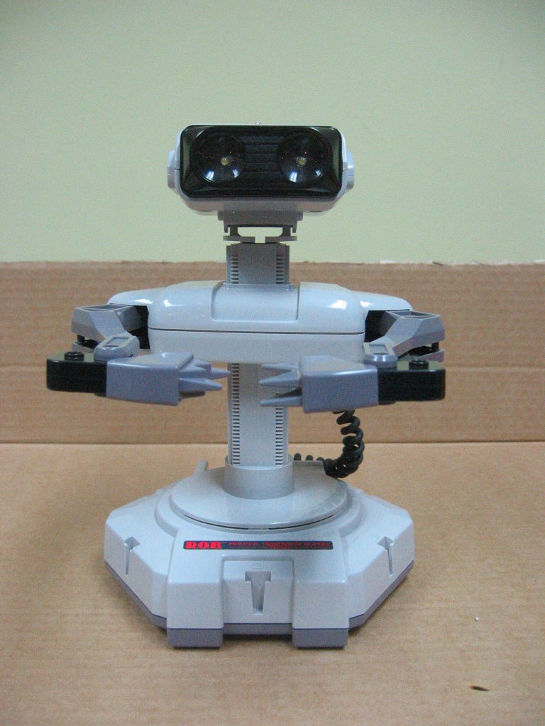
While cleaning out the closet under my basement steps, I dug up the original box for my NES from when I was a kid. The box itself was cool find, but what I found inside was even cooler: a R.O.B.! I'd completely forgot about these, and I was struck with such joy and nostalgia that I decided I was going to keep it on my desk as a decorative ornament.
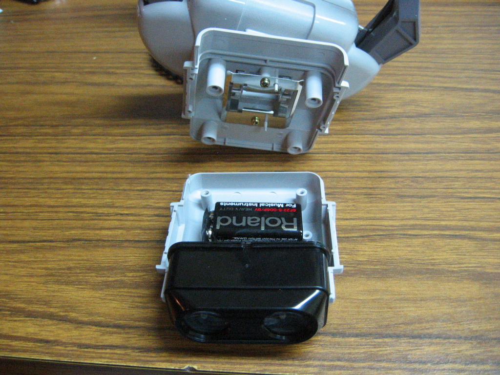
The R.O.B. sat on my desk for a few weeks until I got the good / bad idea of "bringing it back to life" by modding it into a lamp. Illuminating the two "eyes" seemed like a cool idea, so I started disassembling it to get a rough idea of how to make it work. After some unscrewing, I peeked into the head compartment and saw enough space for a 9-volt battery. I also saw that an LED could probably fit in between the plastic lens and the "eye socket". This was enough to convince me to go forward.
Construction
This project was easier to conceptualize than to execute. Figuring out the LED circuit was as easy as punching in some values in this calculator. The hard part was working with delicate components in tiny spaces without breadboard. Drilling a few holes would have made things easier, but I didn't want to risk ruining the R.O.B..
Components:
- Two bright LEDs (rated at a few thousand mcd)
- Resistor(s) to limit current from 9-volt
- A tiny (3 to 5mm) single pole latching toggle switch to fit through a screw hole
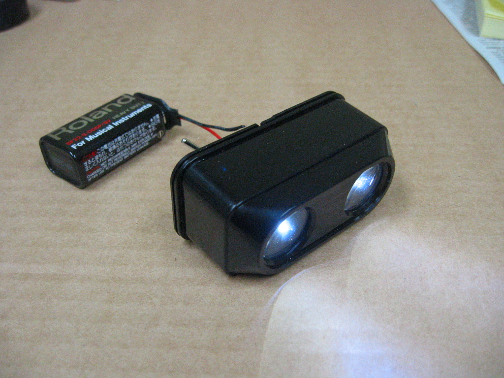
- A 9-volt battery clip
I ended up using 2 RL3-W3030 white 3mm LEDs in series (which required a single 100 ohm resistor) and this SPST toggle switch.
Schematic:
![]()
or: +9V, switch, LED, LED, resistor, –9V
Steps
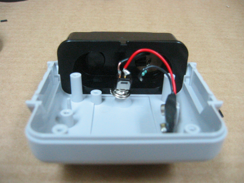
- First, I cut out a piece of cardboard to fit inside the eye socket. I colored it with a black marker to make it less reflective. The cardboard is going to act as a breadboard-esque base for the LED part of the circuit, and it's also going to keep the LEDs in the center of each eye.
- I poked the LED leads through the cardboard. Using electrical tape, I did my best to isolate and insulate the leads from each other to prevent short circuits. I tried to organize them in a fashion that would be the easiest and cleanest to solder.
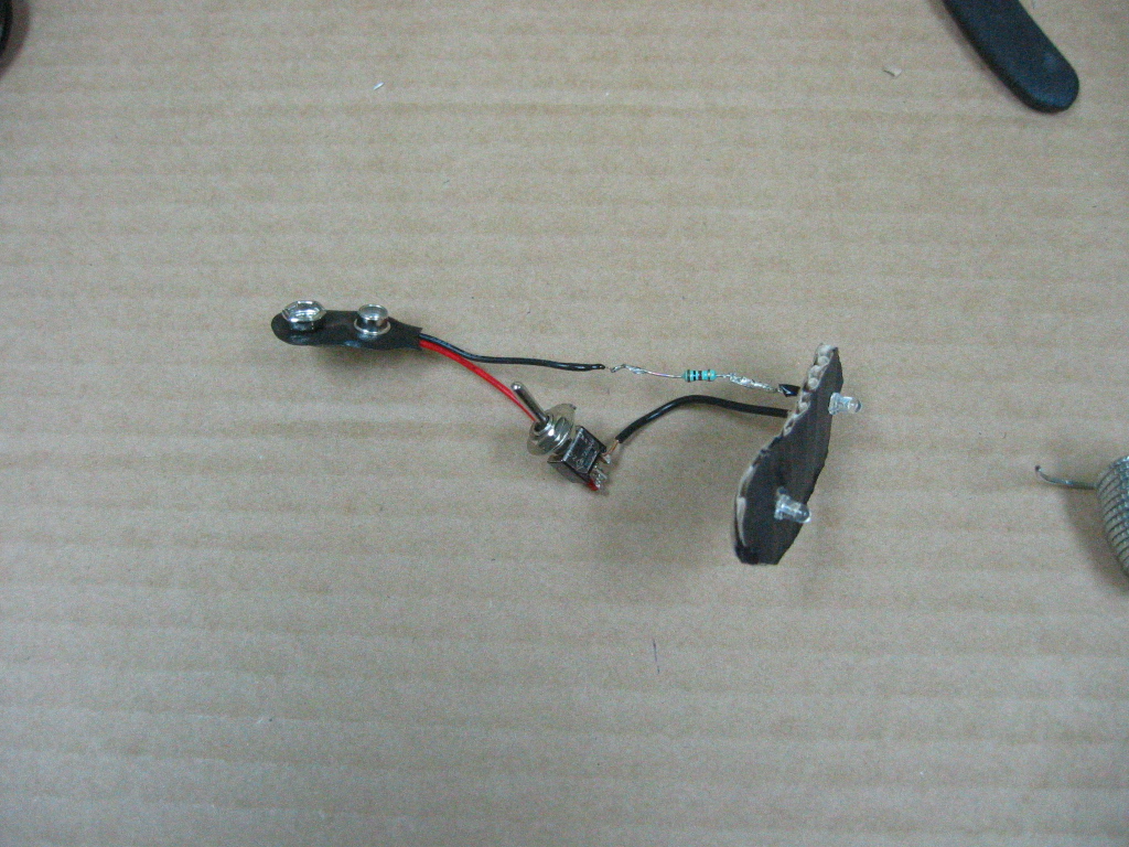
- I soldered the LEDs together, and then extended the anode of the second LED using some hook-up wire so that it would reach the rest of the circuit. The solder joints came out sort of messy but not terrible.
- At this point I did a sanity check to see if the leads fit properly in the eye socket. They did. Forging ahead, I soldered the switch and resistor into the circuit.
- Oops, I used the wrong resistor. I stripped off the old resistor and resoldered the correct one.
- I soldered the last component, the battery clip, into the circuit.
- I popped in a 9-volt and flipped the toggle switch to test the LEDs – nice! Then I put the cardboard part of the circuit back into the R.O.B.'s eye socket to see what the lamp would look like – not bad!
- I attempted epoxying the switch to the under-side of the screw hole on top of R.O.B.'s head, but it didn't hold. Then I reluctantly tried hot glue. I didn't think it was going to be strong enough, but it ended up working well. In retrospect I think this was a good decision because hot glue won't snap as easily as stiffer bonds like epoxy or super glue. It's also less invasive for our fragile robot from the 80s.
- I snapped the 9-volt back onto the battery clip, and prepared to reattach the head.
- R.O.B. reassembled
- R.O.B. better than ever
